Program counter trials and errors
So I started building the program counter this morning, given that I had some free time. I’m using two 74hc245’s connected to four 74hc161. I started off by hooking up the control wiring and clocks for the 161’s, which all went well. Next, I just started wiring up the B<->Q sides, but only after doing all 16 did I realize that I hooked them up wrong! Ah well… For some reason, I went left-right the whole way down, not paying attention to the fact that on the 245’s the bit order is MSB->LSB, and on the 161’s it’s LSB->MSB. So the current bit order instead of being 01234567 is 32107654 ( I think, might be messing this up! Really will have to debug this module, as of right now I literally haven’t tested the ALU, ram, clock(not finished actually), or the PC.)
To fix this without re-wiring those 16 lines, I’ll have to adjust the Data inputs of the 161’s, and the wiring for the bus will certainly be funky.
So the order of the bus, with B0-B7(B0 on the left(MSB), B7 on the right(LSB)), will result in the wiring in the table below.
Pin connection order (the A sides of the 74hc245’s are connected)
| Bus | 74hc245 pin | 74hc161 chip&pin |
|---|---|---|
| B3 | 2 | high, Data input A 3 |
| B2 | 3 | high, Data input B 4 |
| B1 | 4 | high, Data input C 5 |
| B0 | 5 | high, Data input D 6 |
| B7 | 6 | low, Data input A 3 |
| B6 | 7 | low, Data input B 4 |
| B5 | 8 | low, Data input C 5 |
| B4 | 9 | low, Data input D 6 |
The amount of freaking out that just happened was rediculous, and I spent far too long talking to grok(and getting it to realize my layout(which it had issues with at first)) to get that output. But, this should work, and the only weird wiring will be the main bus to the first 245.
But I’ve got to go for a while, I’ll be back this afternoon to hopefully finish up the program counter. Then I intend on finishing up the clock, running all of the power wires, and testing things. That’ll take some time to itself, as I’ll have to setup a couple debugging led breadboards temporarily, as I don’t have leds on these boards(not enough space). That’ll be a bunch of breadboards off to the right of the main board with a ton of purple wire. Hopefully the 100ft of that purple wire is enough, otherwise I’ll be ordering more in a couple months. Probably a good idea to wait on that, I need to stop ordering stuff from Jameco on a weekly basis.
After lunch progress
I’ve decided to wire these up in such a way that I could theoretically convert it to a straight 16-bit PC with a 16-bit main bus by taking away jumpers connecting the 245’s. I don’t know if I ever will do that, as it’ll require making everything else(alu, ram, a boat load of registers) 16 bits, but why not? Wire’s not too expensive. If anything, the next iteration will be 16-bit on a pcb or something.
Evening update
I finished wiring up the program counter and ran double power wires down the whole right side(oh, I also connected the right side together so far)
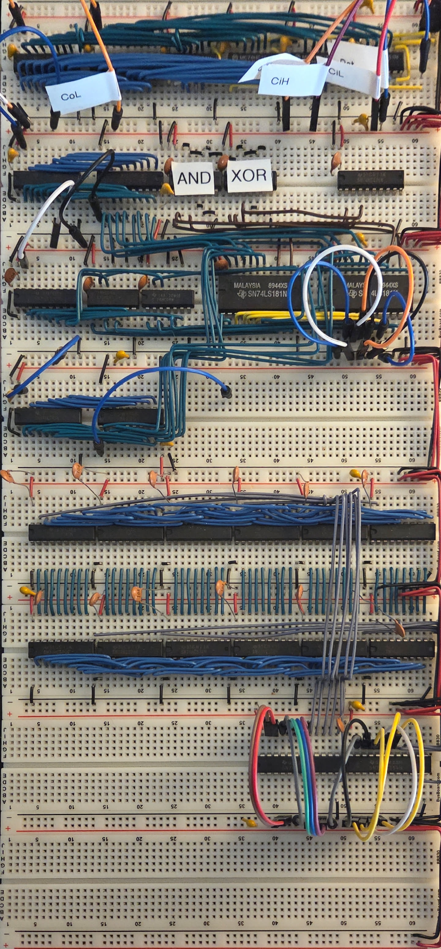
PC, ALU, registers
I’m probably going to call that for the day, tomorrow I intend on finishing the clock(finally, it’s only been a couple weeks), hooking up a temporary bus(I need to find a good size for a board), and start debugging literally everything.
After that, I need to hook up the rest of the control lines going from the 4-16 decoders, and make sure all of those work as intended. The best time to catch the errors that do exist is now, before I have literally everything built. Knowing me, I’ll find some big ones here. But that’s a tomorrow, or perhaps further this week/next weekend issue. Not a today problem.
–cc